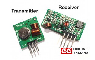
RF Wireless 315 / 433 MHz Receiver Module
- Was RM10.00
-
RM5.50
- Product Code: rf-receiver-module
- Availability: In Stock

| RF Receiver XY--MK-5V |
Arduino |
| GND | GND |
| DATA | - |
| DATA | Analog Pin-0 |
| VCC | 5V |
If all goes to plan, the onboard LED on this Arduino should light up (and go off) at the same time as the onboard LED on the transmitting Arduino. There is a chance that the receiver may pick up stray signals from other transmitting devices using that specific frequency. So you may need to play around with the threshold value to eliminate the "noise". But don't make it too big, or you will eliminate the signal in this experiment. You will also notice a small delay between the two Arduinos.
Arduino sketch - Receiver
/*
  RF Blink - Receiver sketch
     Written by ScottC 17 Jun 2014
     Arduino IDE version 1.0.5
     Website: http://arduinobasics.blogspot.com
     Receiver: XY-MK-5V
     Description: A simple sketch used to test RF transmission/receiver.
 ------------------------------------------------------------- */

 #define rfReceivePin A0  //RF Receiver pin = Analog pin 0
 #define ledPin 13        //Onboard LED = digital pin 13

 unsigned int data = 0;   // variable used to store received data
 const unsigned int upperThreshold = 70;  //upper threshold value
 const unsigned int lowerThreshold = 50;  //lower threshold value

 void setup(){
   pinMode(ledPin, OUTPUT);
   Serial.begin(9600);
 }

 void loop(){
   data=analogRead(rfReceivePin);    //listen for data on Analog pin 0

    if(data>upperThreshold){
     digitalWrite(ledPin, LOW);   //If a LOW signal is received, turn LED OFF
     Serial.println(data);
   }

   if(data<lowerThreshold){
     digitalWrite(ledPin, HIGH);   //If a HIGH signal is received, turn LED ON
     Serial.println(data);
   }
 }
When a HIGH signal is transmitted to the other Arduino. It will produce an AnalogRead = 0.
When a LOW signal is transmitted, it will produce an AnalogRead = 400.
This may vary depending on on your module, and voltage used.
The signals received can be viewed using the Serial Monitor, and can be copied into a spreadsheet to create a chart like this:

You will notice that the HIGH signal (H) is constant, whereas the LOW signal (L) is getting smaller with each cycle. I am not sure why the HIGH signal produces a Analog reading of "0". I would have thought it would have been the other way around. But you can see from the results that a HIGH signal produces a 0 result and a LOW signal produces a value of 400 (roughly).
Tags: RF